Car Battery Charger Diagram
12v Car Battery Charger Circuit Diagram
12v 7ah Smart Battery Charger With Pcb Diagram Engineering Projects
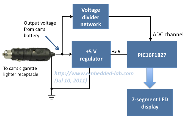
Voltage Monitor For Car S Battery And Its Charging System
12v Battery Charger Circuit Without Transformer

Automatic Nimh Battery Charger Circuit Circuit Diagram
12v Battery Charger Circuits Using Lm317 Lm338 L200
Classic Car Battery Charging Circuit Diagram Under Car Bike
Aug 24 2016 schumacher battery charger wiring diagram.

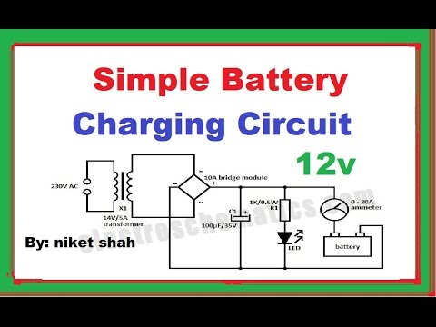
Car battery charger diagram. It tapers off to 4a at 135v 3a at 140v 2a at 145v and 0a at 150v. The circuit will charge automobiles batteries without removing them from their original mounting and no need of. In this unit the full load current of the supply transformerrectifier section was 44a. Description here is the circuit diagram of a simple and straight forward 12 v battery charger circuit with diagram.
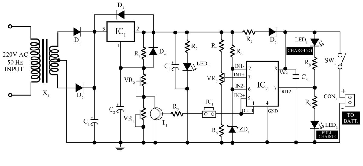
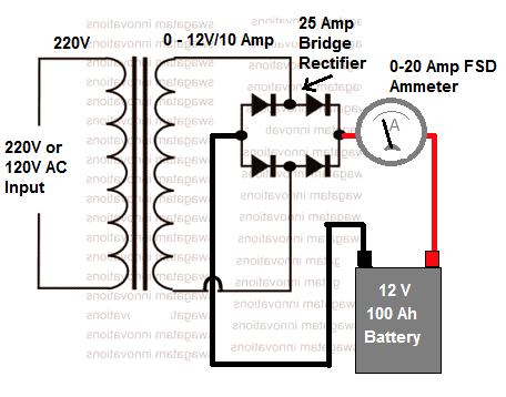
Given below is a very simple circuit that can be used for charging car batteries. The circuit is nothing but a 12v dc power supply with an ammeter for monitoring the charging current. This is a schematic diagram of a full automatic 12v battery charger for charging the batteries of automobiles etc. This circuit has a maximum 2 amperes charging rate.
Stay safe and healthy. Different batteries have different strategies of charging and in this project i will show you how to recharge a lead acid battery using a simple lead acid battery charger circuit. An automotive or car battery charger rarely goes wrong. How to make a 12v battery charger at home.
Just have to understand battery charging requirements only. Once the fine weather starts the family car tends to remain increasingly in the garage. It is designed for 12v batteries. November 05 2019 in.
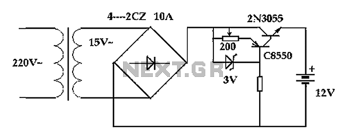
Aug 24 2016 schumacher battery charger wiring diagram. A summer circuits edition on all things outdoors good but what of all the battery powered circuits that remains indoors. Simple automatic battery charger circuit. The main supply voltage 230v 50hz is connected to the primary winding of the center tapped transformer to step down the voltage to 15 0 15v.
Schumacher battery charger wiring diagram. We can use this circuit for all battery. In this circuit there is facility for monitoring the charging current and voltage. The two diodes forms a centre tapped.
Posted thursday april 18 2013 unlike many units this battery charger continuously charges at maximum current tapering off only near full battery voltage. Epsom salt for battery reconditioning product. Automotive circuit diagrams battery charger lcd led display no comments. Check out our resources for adapting to these times.
Constant attention because the circuit will automatically switches from charging current to trickle charge when the. This circuit can be used to charge all type of 12v rechargeable batteries including car batteries. Before proceeding further i want you to know that this circuit is tested in a specific test conditions and we do not guarantee that it will be 100 successful. We use the concept of the circuit.
Use existing products to use more benefits. Automatic car battery charger schematic circuit diagram. This is the first automatic battery charger circuit. A battery charger doesnt contain any moving parts and is simply a device that transforms mains alternating current ac into direct current dc at a much reduced voltage usually 12 volts.
12 volt car battery charger circuit schematic. Please wash your hands and practise social distancing. Circuit diagram of automatic battery charger this automatic battery charger circuit is mainly involves two sections power supply section and load comparison section. The transformer t1 steps.
