Car Battery Charger Circuit

Simple Battery Charger Circuit Simple Battery Circuit Diagram
12v 100ah Battery Charger Circuit Diy Electronics Projects
12v Car Battery Charger Circuit Diagram
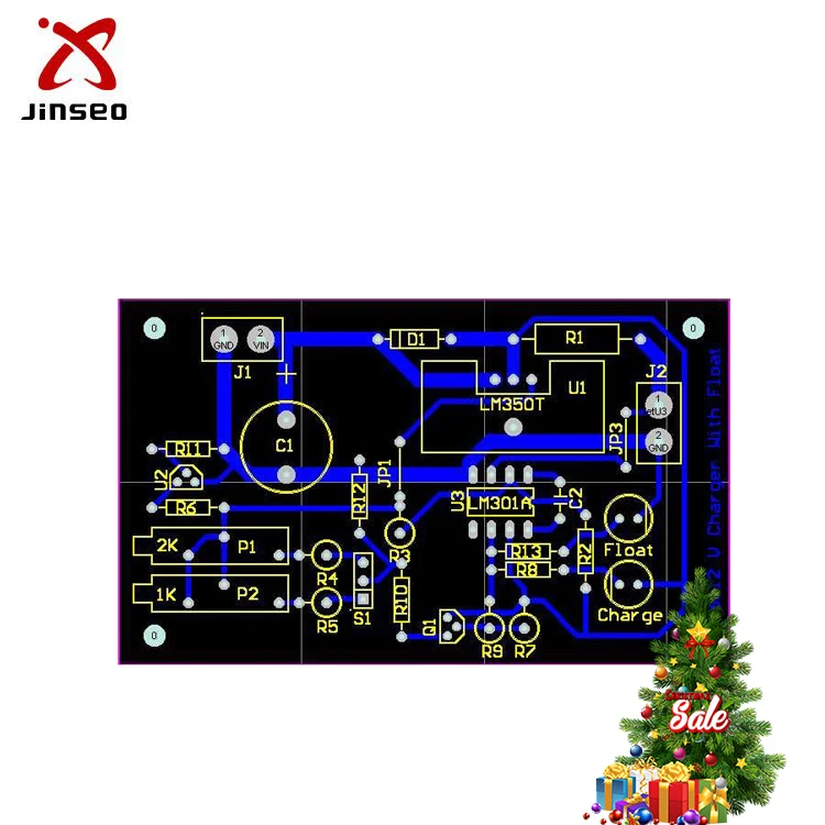
12v Car Battery Charger Circuit Pcb Board

Auto Battery Charger Circuit Using 555 English Version Youtube
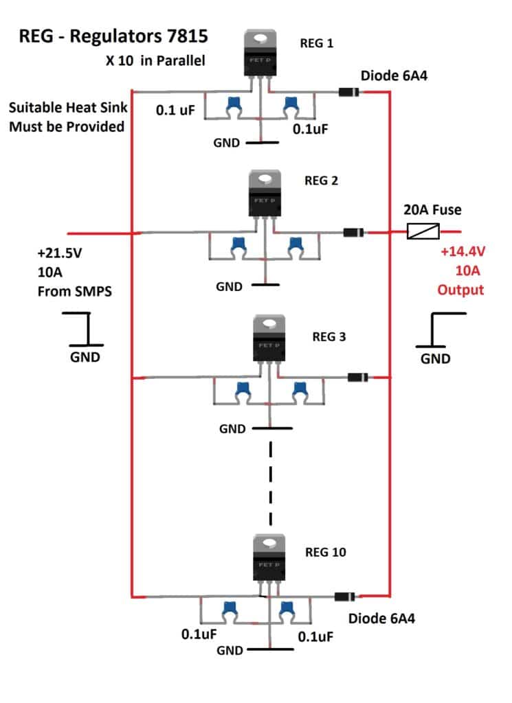
Adjustable Car Battery Charger Circuit Power Supply Circuit

Regulated Car Battery Charger Circuit For Garage Mechanics
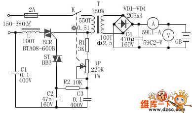
In the battery charger using auto dry battery charger using scr circuit above wanted to clarify regarding the maximum current which would pass through scr1.
Car battery charger circuit. I have posted many battery charger circuits in this site some are easy to build but less efficient while some are too sophisticated involving complex construction steps. The circuit is nothing but a 12v dc power supply with an ammeter for monitoring the charging current. This battery voltage is constantly monitored by a feedback. In this unit the full load current of the supply transformerrectifier section was 44a.
Car battery charger circuit working principle. The one posted here is possibly the easiset with its concept and also is extremely easy to build. In fact if you had all the. This would forward bias the scr1 since cathode is at zero voltage.
November 05 2019 in. Then when the circuit is powered on the peak ac voltage at the anode of the scr1 would be 21v 15v rms. It tapers off to 4a at 135v 3a at 140v 2a at 145v and 0a at 150v. This circuit can be used to charge all type of 12v rechargeable batteries including car batteries.
A summer circuits edition on all things outdoors good but what of all the battery powered circuits that remains indoors. Make a battery charger in 15 minutes. Automatic car battery charger schematic circuit diagram. The battery is charged from a 230v 50hz ac mains supply.
Assuming we are connecting a discharged lead acid battery. Automotive circuit diagrams battery charger lcd led display no comments. Posted thursday april 18 2013 unlike many units this battery charger continuously charges at maximum current tapering off only near full battery voltage. Last updated on july 29 2019 by swagatam 65 comments.
Circuit diagram of automatic battery charger this automatic battery charger circuit is mainly involves two sections power supply section and load comparison section. Here is the circuit diagram of a simple and straight forward 12 v battery charger circuit with diagram. This is a simple car battery charger with indication. The main supply voltage 230v 50hz is connected to the primary winding of the center tapped transformer to step down the voltage to 15 0 15v.
This ac voltage is rectified and filtered to obtain an unregulated dc voltage used to charge the battery through a relay. Once the fine weather starts the family car tends to remain increasingly in the garage. Regulated car battery charger circuit for garage mechanics last updated on february 10 2020 by swagatam 8 comments if you are an automotive technician vehicle technician or a motor mechanic you may find this cheap yet powerful car battery charger circuit extremely handy as it can be used for charging all types of car and motorcycle battery overnight with minimum effort.
